
1. Produkt överview
The YUHANUS Electric Drop Bolt Lock is designed for use in access control systems, providing enhanced security for various door types. This model operates in NO Mode (Fail-Security), meaning the lock is in a locked state by default when power is off. It will only unlock when power is applied and an authorized signal (e.g., from a push button or remote controller) is received. It features a time delay function for controlled access.
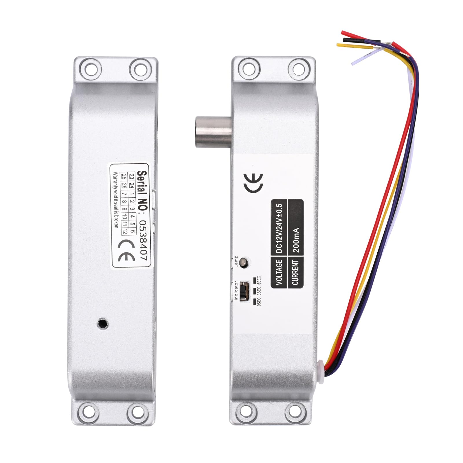
Image 1.1: The YUHANUS Electric Drop Bolt Lock, showcasing its compact design and wiring.
2. Säkerhetsinformation
- Ensure all power is disconnected before installation or maintenance to prevent electrical shock.
- Installation should be performed by qualified personnel or under professional supervision.
- Verifiera korrekt voltage (DC 12V) and current specifications before connecting to a power source. Incorrect voltage kan skada enheten.
- Do not expose the lock to excessive moisture or extreme temperatures.
- Följ alltid lokala elföreskrifter och -föreskrifter.
3. Paketets innehåll
Kontrollera paketet för att säkerställa att alla artiklar finns med:
- Electric Mortise Lock Unit
- Panellock
- Induction Lock Component
- Mounting Screws (Set)
- Bruksanvisning (detta dokument)
- Intyg om överensstämmelse
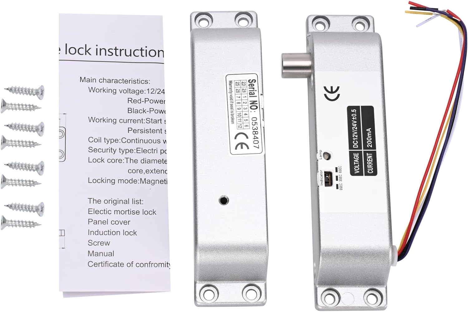
Image 3.1: Contents typically included in the product package, showing the lock units, screws, and a small instruction sheet.
4. Specifikationer
| Särdrag | Specifikation |
|---|---|
| Modellnamn | Electric-Bolt-Lock01-NO |
| Operation Voltage | DC 12V |
| Driftström | 200mA |
| Låstyp | Drop Bolt, Fail-Security (NO Mode) |
| Tidsfördröjning | 0s / 3s / 6s (Adjustable) |
| Material | Aluminium |
| Mått (L x B x H) | 6 x 1.3 x 1 tum (ca 150 mm x 33 mm x 27 mm) |
| Monteringstyp | Ytmonterad |
| Lämpliga dörrtyper | Wooden door, metal door, fireproof door, etc. |

Image 4.1: Detailed dimensions of the electric drop bolt lock for installation planning.
5. Installation och installation
5.1 Montering av låset
- Förbered dörren och karmen: Identify the desired mounting location on the door frame and the corresponding position on the door for the bolt to engage. The lock is surface-mounted.
- Markera borrpunkter: Use the lock unit as a template to mark the screw holes on both the door frame and the door.
- Borra pilothål: Borra lämpliga förborrhål för monteringsskruvarna.
- Säkra låset: Attach the main lock unit to the door frame and the induction lock component to the door using the provided screws. Ensure proper alignment for smooth bolt operation.
5.2 Kopplingsinstruktioner
The electric drop bolt lock requires connection to a DC 12V power supply and an access control system. Refer to the wiring diagram below for proper connections.
- Röd kabel: Anslut till +12V terminal of your power supply control.
- Svart kabel: Anslut till GND (Ground) terminal of your power supply control.
- Purple Cable: Anslut till INGA (Normally Open) terminal in your power supply control or access control panel. This connection is crucial for the Fail-Security (NO Mode) operation.
- Andra kablar: Yellow and White cables are typically for door status feedback (NC/COM), which may or may not be used depending on your access control system's requirements. Consult your access control system manual for these connections.

Image 5.1: Wiring diagram illustrating connections for the electric bolt lock within a typical access control system, including power supply, keypad, and exit button.
6. Bruksanvisning
6.1 NO Mode (Fail-Security) Operation
This electric drop bolt lock operates in NO Mode (Fail-Security). This means:
- When there is no power, or in case of a power failure, the lock remains in a locked state.
- The lock will only unlock when power is supplied to the lock and an authorized signal is received from the access control system (e.g., pressing a push button, using a remote controller, or entering a code on a keypad).
6.2 Time Delay Function
The lock features an adjustable time delay function, which controls how long the door remains unlocked after an authorized signal is received. The delay can be set to 0 seconds, 3 seconds, or 6 seconds.
To adjust the time delay, locate the small switch or jumper on the side of the lock unit (refer to Image 6.1). Move the switch or adjust the jumpers to select the desired delay setting (0s, 3s, or 6s).

Bild 6.1: Närbild view of the time delay adjustment switch on the lock unit, allowing selection between 0, 3, and 6 seconds.
7. Underhåll
- Rengöring: Wipe the lock's exterior with a soft, dry cloth. Avoid using abrasive cleaners or solvents that could damage the finish or internal components.
- Inspektion: Periodically check all mounting screws to ensure they are tight. Inspect wiring for any signs of wear, fraying, or loose connections.
- Funktionstest: Regularly test the lock's operation with your access control system to ensure it locks and unlocks correctly and that the time delay functions as expected.
8. Felsökning
| Problem | Möjlig orsak | Lösning |
|---|---|---|
| Lock does not engage (stay locked) | No power to the lock; Incorrect wiring for NO Mode. | Check power supply (DC 12V). Verify Red and Black wire connections. Ensure Purple wire is correctly connected to NO terminal. |
| Lock does not disengage (unlock) | No signal from access control; Insufficient power; Faulty access control component. | Confirm access control system is functioning. Check power supply voltage. Inspect Purple wire connection. |
| Time delay not working correctly | Incorrect time delay setting. | Adjust the time delay switch/jumper on the lock unit to the desired setting (0s, 3s, or 6s). |
| Lock is loose or misaligned | Loose mounting screws; Improper initial installation. | Tighten all mounting screws. If misalignment persists, re-evaluate mounting positions and re-install if necessary. |
9. Garanti och support
For warranty information or technical support, please contact your retailer or the manufacturer directly. Keep your purchase receipt as proof of purchase for any warranty claims.
Manufacturer: YuHan
Modellnummer: 769894490600