1. Introduktion och överview
The Banner Engineering M18TUP14 is an industrial temperature sensor designed for precise temperature measurement in various industrial applications. This sensor features a 1 Germanium Lens, providing accurate readings within a temperature range of -20°C to +300°C. It offers an analog 0-10V output for continuous temperature monitoring and a PNP alarm output for threshold detection. The robust design, including an IP67 rating, ensures reliable performance in demanding environments. This manual provides essential information for the safe and effective installation, operation, and maintenance of your M18TUP14 sensor.
2. Säkerhetsinformation
Read all instructions carefully before installing or operating the M18TUP14 sensor. Failure to follow these instructions may result in product damage, property damage, or serious injury.
- Installation and maintenance should only be performed by qualified personnel familiar with industrial electrical systems and safety procedures.
- Ensure that power is disconnected from the system before performing any wiring or maintenance.
- Verify that the operating supply voltage (12V to 30V DC) is within the specified range to prevent damage to the sensor.
- Protect the sensor from physical impact and extreme environmental conditions beyond its specified operating limits.
- Do not attempt to modify or repair the sensor. Refer all servicing to authorized service personnel.
3. Paketets innehåll
Kontrollera att alla föremål finns och är oskadade vid uppackning:
- 1 x M18TUP14 Industrial Temperature Sensor
Om några komponenter saknas eller är skadade, kontakta din leverantör omedelbart.
4. Specifikationer
| Modell | M18TUP14 |
| Tillverkare | Bannerteknik |
| Temperaturområde | -20°C till +300°C (-4°F till +572°F) |
| Drifttillförsel Voltage | 12V till 30V DC |
| Utgångstyp | Analog 0-10V, PNP Alarm |
| Linstyp | 1 Germanium Lens |
| Kabellängd | 2 m (6.5 fot) |
| IP-betyg | IP67 |
| Objektets vikt | 6.99 pund (ca 3.17 kg) |
5. Installation och installation
Proper installation is crucial for the accurate and reliable operation of the M18TUP14 sensor.
5.1 Montering
The M18TUP14 sensor features an M18 threaded barrel for easy mounting. Use appropriate mounting hardware (not included) to secure the sensor in the desired location. Ensure the sensor's lens is unobstructed and has a clear line of sight to the target area for temperature measurement. The IP67 rating ensures protection against dust and temporary immersion in water, making it suitable for harsh industrial environments.
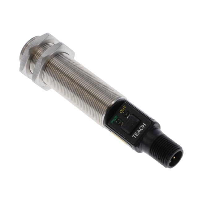
Figure 1: M18TUP14 Industrial Temperature Sensor. The image displays the cylindrical, threaded body of the sensor, with a black end housing the power (PWR) and output (OUT) indicator LEDs, and a 'TEACH' button. The sensor terminates in a threaded connector for wiring.
5.2 Kabeldragning
Connect the sensor to your control system according to the following general guidelines. Refer to the specific wiring diagram provided with your sensor for detailed connections. Ensure power is OFF before wiring.
- Strömförsörjning: Connect the sensor to a stable 12V to 30V DC power source. Observe correct polarity.
- Analog Output (0-10V): Connect the analog output wire to the corresponding analog input on your PLC, data acquisition system, or controller. This output provides a continuous voltage signal proportional to the measured temperature.
- PNP Alarm Output: Connect the PNP alarm output wire to a digital input on your controller. This output will switch high (to supply voltage) when the temperature exceeds a configured threshold.
- Jord: Ensure a proper ground connection for stable operation and safety.
6. Drift
Once installed and wired, the M18TUP14 sensor is ready for operation.
6.1 Power-Up and Indicators
Upon applying power, the PWR (Power) indicator LED on the sensor will illuminate, typically green, indicating that the sensor is receiving power. The UT (Output) indicator LED will illuminate when the PNP alarm output is active (i.e., when the measured temperature exceeds the set alarm threshold).
6.2 Analog Output Reading
The 0-10V analog output provides a continuous representation of the measured temperature. You will need to scale this voltage reading in your control system (PLC, HMI, etc.) to convert it into a temperature value (e.g., degrees Celsius or Fahrenheit) based on the sensor's specified temperature range (-20°C to +300°C).
Till exempelample, 0V might correspond to -20°C and 10V to +300°C. Consult the sensor's data sheet for the exact scaling factor if not provided here.
6.3 Setting Alarm Threshold (TEACH Function)
The 'TEACH' button on the sensor is used to set the PNP alarm threshold. The exact procedure may vary slightly, but typically involves:
- Place the sensor in the environment or at the temperature you wish to set as the alarm threshold.
- Press and hold the 'TEACH' button for a specified duration (e.g., 2-5 seconds) until the OUT indicator flashes, indicating it has learned the new threshold.
- Release the button. The sensor is now configured, and the PNP alarm will activate when the temperature exceeds this newly taught value.
Refer to the detailed programming instructions in the full Banner Engineering product manual for advanced teaching modes or specific timing requirements.
7. Underhåll
The M18TUP14 sensor is designed for minimal maintenance. However, periodic checks can ensure optimal performance and longevity.
- Rengöring: Keep the sensor lens clean and free from dust, dirt, or debris. Use a soft, lint-free cloth and, if necessary, a mild cleaning solution. Avoid abrasive materials or harsh chemicals that could damage the lens or housing.
- Inspektion: Periodically inspect the sensor and its wiring for any signs of physical damage, corrosion, or loose connections. Ensure mounting is secure.
- Miljöförhållanden: Kontrollera att driftsmiljön håller sig inom de angivna temperatur- och luftfuktighetsgränserna.
8. Felsökning
If you encounter issues with your M18TUP14 sensor, consider the following common troubleshooting steps:
| Problem | Möjlig orsak | Lösning |
|---|---|---|
| Ingen ström (strömförsörjningslampan släckt) | Ingen strömförsörjning; Felaktig kabeldragning; Felaktig strömförsörjning. | Kontrollera strömanslutningar och volymtage (12-30V DC). Verify wiring polarity. Test power supply. |
| Incorrect Analog Output Reading | Sensor lens obstructed/dirty; Incorrect scaling in controller; Sensor outside temperature range. | Clean sensor lens. Verify scaling parameters in your control system. Ensure target temperature is within -20°C to +300°C. |
| PNP Alarm Not Triggering | Incorrect alarm threshold set; Wiring issue; Temperature not reaching threshold. | Re-teach the alarm threshold using the 'TEACH' button. Check PNP output wiring. Verify actual temperature. |
| Intermittent Readings | Loose wiring connections; Electrical interference; Unstable power supply. | Secure all wiring connections. Ensure proper grounding. Use shielded cables if interference is suspected. |
If the problem persists after attempting these steps, contact Banner Engineering technical support or your authorized distributor for further assistance.
9. Garanti och support
For information regarding the warranty of your M18TUP14 Industrial Temperature Sensor, please refer to the warranty statement provided by Banner Engineering or contact your point of purchase (e.g., Neutron USA). Technical support and additional resources can typically be found on the official Banner Engineering webwebbplatsen eller genom att kontakta deras kundtjänstavdelning.
Tillverkare: Bannerteknik
ASIN: B0F4JSFBPY