1. Introduktion
This manual provides detailed instructions for the installation, operation, and maintenance of the FTVOGUE Multifunction Time Delay Relay Module. This module is designed for industrial automation control, offering 20 programmable functions per channel and a wide operating voltage range of DC 8V to 36V. Please read this manual thoroughly before use to ensure proper functionality and safety.

Figure 1.1: FTVOGUE Multifunction Time Delay Relay Module. This image shows the top view of the relay module, highlighting its compact design and various components including the digital display and control buttons.
2. Säkerhetsinformation
- Se till att strömförsörjningen voltage is within the specified range (DC 8V to 36V) to prevent damage to the module.
- Always disconnect power before making any wiring connections or disconnections.
- Wiring should be performed by qualified personnel to avoid electrical hazards.
- Utsätt inte modulen för fukt, extrema temperaturer eller korrosiva miljöer.
- The module features power anti-reverse connection protection, but always double-check polarity during installation.
3. Produktfunktioner
- Mångsidig kontroll: Offers 4 channels with 20 programmable functions per channel for complex automation tasks.
- Wide Voltage Range & Safety: Operates on 8-36V DC power with built-in power anti-reverse connection protection.
- Precise Timing Control: Programmable timing functions down to 1-second intervals with less than 1% error.
- Enhanced Visual Feedback: Clear power and relay status indicators via bright LED lights.
- Energieffektiv design: Automatic power-saving technology and memory retention for settings during power cycles.

Figure 3.1: Multifunction Relay Module. This image highlights the module's power indicator light and relay suction indicator lights, providing visual feedback on its operational status.
4. Paketets innehåll
- 1 x FTVOGUE Multifunction Time Delay Relay Module
5. Modul överview and Port Description
The module features various ports for power input, signal input, and relay load output. Understanding these connections is crucial for proper setup.

Figure 5.1: Module Port Layout. This image provides a clear top-down view of the relay module, detailing the VIN, GND, OFF, COM, IN1-IN4 terminals, and the relay load output connections.
Modul Voltage/Signal Input Terminal (8-line interfaces):
- VIN: DC positive pole for power input.
- GND: DC negative pole for power input.
- OFF: Power control terminal.
- COM: Common end of photoelectric isolation signal input.
- IN1-IN4: Input signal detection interfaces.
Notera: The input signal detection interfaces (IN1-IN4) can be configured for either active-high or active-low operation. This selection is made via the COM port. If COM is connected to 'H' (High), IN1-IN4 will be active high. If COM is connected to 'L' (Low), IN1-IN4 will be active low.
Relay Load Output Terminal (12-wire interface):
These terminals are used to connect the devices or circuits that the relays will control. Each relay has normally open (NO), normally closed (NC), and common (COM) contacts.

Figure 5.2: Module Bottom View. This image displays the underside of the relay module, showing the solder points and circuit board traces, which can be useful for understanding the internal layout.
6. Inställning
6.1 Strömanslutning
- Connect the positive terminal of your DC 8V-36V power supply to the VIN terminal on the module.
- Connect the negative terminal of your DC power supply to the GND terminal on the module.
- Ensure all power connections are secure and correct polarity is observed, despite the anti-reverse protection.
6.2 Signalingångsanslutning
- Determine if your input signals are active-high or active-low.
- For active-high signals, connect the COM terminal to a high logic level (e.g., VCC).
- For active-low signals, connect the COM terminal to a low logic level (e.g., GND).
- Connect your control signals to the respective IN1, IN2, IN3, och IN4 terminaler.
6.3 Relay Load Connection
- Identify the common (COM), normally open (NO), and normally closed (NC) contacts for each relay.
- Connect your load device according to your application requirements (e.g., connect one side of the load to the relay's COM and the other side to NO for normally open operation).
- Se till att strömmen och voltage ratings of your loads do not exceed the relay's specifications (e.g., 10A 250VAC / 10A 30VDC).
7. Bruksanvisning
The FTVOGUE Multifunction Time Delay Relay Module offers 20 distinct operating functions, configurable via the onboard buttons and displayed on the 4-digit LED segment display.
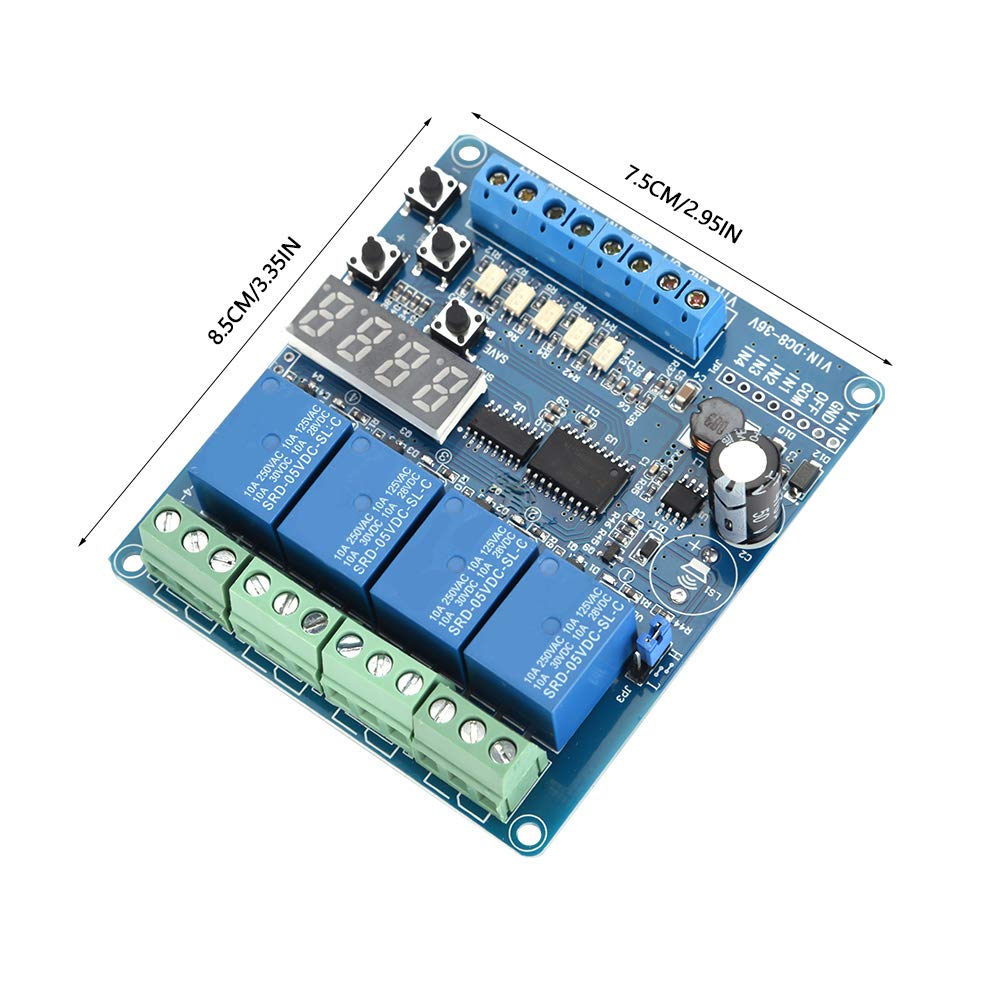
Figure 7.1: Relay Module with Dimensions. This image shows the physical dimensions of the module (8.5cm x 7.5cm), which is helpful for installation planning.
7.1 Function Selection and Parameter Setting
- The module typically features buttons labeled 'SET', '+', '-', and 'SAVE' (or similar) for navigation and parameter adjustment.
- Press the 'SET' button to enter the function selection mode. The LED display will show the current function number.
- Use the '+' and '-' buttons to cycle through the 20 available functions. Each function corresponds to a specific timing or control logic.
- Once a function is selected, press 'SET' again to enter parameter adjustment mode for that function.
- Use '+' and '-' to adjust timing values (e.g., delay time, pulse width) or other function-specific parameters. The timing can be set with 1-second precision.
- After setting all parameters, press the 'SAVE' button to store the configuration. The module will retain these settings even after power cycles.
7.2 LED-indikatorer
- Ström LED: Illuminates when the module is powered on.
- Relay Status LEDs: Individual LEDs for each relay indicate its current state (e.g., ON when the relay is activated, OFF when deactivated). These provide immediate visual confirmation of relay operation.
8. Underhåll
- Håll modulen ren och fri från damm och skräp. Använd en mjuk, torr trasa för rengöring.
- Regularly inspect wiring connections for looseness or corrosion.
- Förvara modulen på en torr och sval plats när den inte används.
- Avoid applying excessive force to the terminals or buttons.
9. Felsökning
- Modulen slås inte på: Kontrollera strömförsörjning voltage and polarity (VIN/GND connections). Ensure the power control terminal (OFF) is correctly configured if used.
- Relay not activating: Verify input signal (IN1-IN4) is correct and COM port is set for active-high/low accordingly. Check the selected function and its parameters. Ensure the load is correctly wired to the relay contacts.
- Felaktig tidpunkt: Re-enter parameter adjustment mode and verify the set timing values. Ensure the correct function is selected.
- Inställningarna sparas inte: Ensure the 'SAVE' button (or equivalent) is pressed after making changes.
10. Specifikationer
| Specifikation | Värde |
|---|---|
| Varumärke | FTVOGUE |
| Modell | FTVOGUErxcag3y2up |
| Artikelnummer | FTVOGUErxcag3y2up |
| ASIN | B0GSC5S78P |
| Tillverkare | FTVOGUE |
| Strömförsörjning Voltage | DC 8V till 36V |
| Antal funktioner | 20 per kanal |
| Timing Accuracy Error | Mindre än 1 % |
| Kontakta Aktuellt betyg | 20 Amps |
| Aktuellt betyg | 2 Amps (likely control current, not load) |
| Kontakttyp | Metall |
| Kontaktmaterial | Se Detaljer |
| Anslutningstyp | Usb_2_0 (This appears to be an error in source data, likely refers to terminal blocks) |
| Monteringstyp | Väggfäste |
| Specifikation Met | Iso 9001 |
| Material | ABS |
| Storlek | Cirka 85 x 75 mm / 3.35 x 2.95 tum |
| Vikt | Ca. 88g |
11. Garanti och support
For warranty information or technical support, please refer to the product packaging or contact your retailer/seller directly. Keep your purchase receipt as proof of purchase.